Precision Op Amp Gain Adjustment with DACs
op amp DAC gain adjustment operational amplifier basics
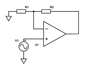
Basic non-inverting operational amplifier design involves a feedback resistor and a gain resistor. These are shown in the figure below as R2 as the feedback resistor and R1 as the gain resistor. The formula for calculating the gain is;
\begin{align} Gain = \frac{R_2}{R_1} + 1 \end{align}
It would be nice to adjust the gain of this amplifier. This can be done achieved easily with a potentiometer in place of R1 or R2. Digital potentiometers are even an option for remote control of the gain. Potentiometers though, give only a coarse adjustment.
Here, we will investigate the use of a digital to analogue converter (DAC) to fine tune the gain of an amplifier. In the image below, $V_2$ is a DAC.

The op amp will try its best to ensure that the inverting terminal voltage is equal to the non inverting terminal. It does this by increasing or decreasing its current output into the feedback loop resulting in a potential across the feedback resistors.
In an ideal world no current flows into the inverting terminal of the op amp so we can ignore this path and assume the central node is equal to $V_1$. This leaves us with current flow through $R_1$, $R_2$ and $R_3$
This circuit can be solved using Kirchoff’s current law. It states that all current entering a node must exit. I.e the sum of currents must be equal to zero.
Derivation
\begin{align} \frac{V_1 - V_o}{R_2} + \frac{V_1}{R_1} + \frac{V_1 - V_2}{R_3} = 0 \end{align}
\begin{align} \frac{V_1}{R_2} - \frac{V_o}{R_2} + \frac{V_1}{R_1} + \frac{V_1}{R_3} - \frac{V_2}{R_3} = 0 \end{align}
\begin{align} V_1(\frac{1}{R_1} + \frac{1}{R_2} + \frac{1}{R_3}) - \frac{V_o}{R_2} - \frac{V_2}{R_3} = 0 \end{align}
\begin{align} R_2 V_1(\frac{1}{R_1} + \frac{1}{R_2} + \frac{1}{R_3}) - \frac{V_2 R_2}{R_3} = V_o \end{align}
\begin{align} V_1(1 + \frac{R_2}{R_1} + \frac{R_2}{R_3}) - \frac{V_2 R_2}{R_3} = V_o \end{align}
Lets use some real numbers and components. DACs range in their resolution and supply voltages so lets go with a 12-bit 5V DAC. R1 = R2 = 2k5, R3 = 200k, and V1 = 1V.
The full range (0-5V) from the DAC would give a voltage output between 1.95V to 2.0125V in steps of 15.2$\mu$V (2.0125 - 1.95)/212.
comments powered by Disqus